My Coachmen Pathfinder RV, motor home has an ATS5070 Automatic Transfer Switch.
It malfunctioned. I am writing this long after the time of the failure and don't recall for sure but the failure MAY have been related to when our house took a lightening hit. We were lucky and only a few devices were fried.
Anyway, for more than a year, I manually connected the correct wires when I needed to run the generator. When I retired Aug 1, 2015 I finally had a chance to work on my backlog of special projects like this one.
To start, lets consider the wire colors. In my unit all wires are the correct colors. Don't assume this is true on your unit, measure it and confirm before getting too close! When these circuits are live, there is dangerous electricity present. You NEED TO MEASURE to confirm that conditions are as expected before starting work. Also, be sure that nobody is around to 'turn on' or to 'plug in' the circuit that you are working on. This could cause an unexpected dangerous condition.
Black = L1, HOT wire
Red = L2, HOT wire
White = Return (or Neutral)
Green = ground
Bare (no insulation) = ground
L1 and L2 are HOT!!!
The White Neutral, also called the Return wire should NOT be Hot!
HOT means that if you connect a voltmeter from this wire to ground you will read that electricity is present. So, when the circuits are active, you should read about 120V from either the Black or the Red wire to ground.
The White wire is the Return wire. Electricity must have a way to 'come' and it must have a way to 'go back'. If one of the two are not connected, the light won't come on, the motor won't run. The White wire is the path the electricity uses to go back, hence the term Return wire. The Black or the Red wire is the path for the electricity to 'come'.
Putting a voltmeter across the Black and the White wire should read about 120V.
Putting a voltmeter across the Red and the White wire should read about 120V.
Putting a voltmeter across the White and the Ground should read 0V. It is dangerous if this is NOT 0 Volts, get a professional to look at ASAP!
In a property 'main' breaker box, the one box with the wires coming from the power company electric service, there is one bus where both the white return wires and the bare/green ground wires are connected. In this one main box they are connected together.
In 'satelite' breaker boxes, the white wires and the bare/green gound wires have their own separate connection buses. In satelite breaker boxes, the white wires and the bare/green wires are NOT connected together. The breaker box in a camper is such a satelite box and should have separate white return and bare/green ground buses. When they are NOT connected together it is possible to have a voltage difference between these wire types. If you have such a voltage difference, you want to get this fixed ASAP.
One final item, if you put a voltmeter across the Red and the Black wires, you might get about 220V (like the red & black in to your home). On my generator, L1 and L2 are 'in phase' so in this case reading across these two wires reads at 0V difference between these two wires. Please be strongly aware that these wires are both at 120 V (to ground) it is simply that that are both at the same 120V, they are both very HOT, at the same hotness, and both deserve appropriate respect!
In the ATS 5070 there are:
2 Heavy Duty Relays
1 Bridge Rectifier, RS207L
1 Time Delay Relay, E174797
1 SPDT switch attached to the Heavy Duty Relay that controls the Wht and Blu wires
The Heavy Duty Relays connect the control panel (the camper AC wiring) to:
either the cord (that plugs into the campground power outlet)
or the generator.
These are effectively electrically activated big DPDT switches. (DPDT = double pole, double throw)
The 'no electricity' state of the Heavy Duty Relays is to connect the Cord to the Control Panel, to the internal camper wires.
These relays stay in this state where the Cord is connected to the Control Panel unless/until the generator applys power and the Bridge Rectifier and the Time Delay Relay work their magic.
The Bridge Rectifier has 4 terminal connectors:
2 AC line inputs
a + DC output
and a - DC output.
The job that the Bridge Rectifier does is to change a little bit of AC electricity from the generator into + and - (plus and minus) DC electricity.
This little bit of DC electricity does two jobs:
it tells the Time Delay Relay that electricity from the generator is present and to begin a 'timing' cycle
and it will provide the electricity to the heavy duty relay coils that will cause those relays to change where the control panel electricity comes from (from either the cord or from the generator). It is the power to 'switch' those Heavy Duty Relays.
The Time Delay Relay waits for DC electricity coming from the Bridge Rectifier.
When it detects DC electricity from the Bridge Rectifier, it begins a timer cycle that lasts maybe a couple minutes at most (I haven't timed this).
When the timer completes it's cycle, then the internal relay (inside the Time Delay Relay) switches and applies DC voltage to the coil of the Heavy Duty Relay that controls the Wht and Blu wires.
This causes this relay to switch, disconnecting the Cord and connecting the Generator WHITE neutral return wires to the internal house wiring White wires.
This also causes that attached SPDT switch to connect the second Heavy Duty Relay coil to the DC output from the Time Delay Relay.
The second Heavy Duty Relay now has electricity on it's coil and it now also switches, disconnecting the Cord and connecting the Generator Red and Black wires to the internal house wiring.
Note that this second Heavy Duty Relay switches a fraction of a second after the first Heavy Duty Relay switches. The returns are connected first then the hots are switched over.
When generator electricity stops arriving (when generator is turned off), the Heavy Duty Relays switch back to their deactivated, 'no electricity' (no Generator electricity) state where the Cord wires are connected to the Control Panel, the camper AC wires.
It is a over simplification but it is valid to think of the Heavy Duty Relays as being big switches that switch over when generator electricity is applied to their coils. In the absence of generator electricity, these relays connect the Cord electricity to the house wires. When Generator electricity is present to cause the relays activate, to change states, they then connect the Generator electricity to the house wires.
Upon testing my non-functional ATS5070, I discovered that my Bridge Rectifier did not show correct resistance readings. I was within reasonable driving distance to a Radio Shack and they stock a 4A 400V full waver Bridge Rectifier that has close enough specs to work in this device. I bought one, dropped it in, applied AC to generator L1 and Wht leads, and tested for appropriate Bridge Rectifier function (that would be reading a Plus voltage on the + pin and a - voltage on the - pin) and while I was reading those values, the big relays toggled over to their other state. Urica! I installed it in my RV and to my profound joy, it once again is working correctly. No more hand jumping the generator wire to the camper wires when I need to run the genny.
I did NOT find the exact Time Delay Relay part number on the Internet. There are some time delay relays that seem like they should work OK.
I will buy and keep in stock a Bridge Rectifier and a Time Delay Relay anticipating that since I brought my raincoat, it won't rain.
(I have purchased a ICM102 'Delay on Make Timer' to replace the E174797 Time Delay Relay if it ever fails. This replacement device will provide similar functionality. It will need to be correctly wired and is NOT just a drop-in replacement either electrically or physically.)
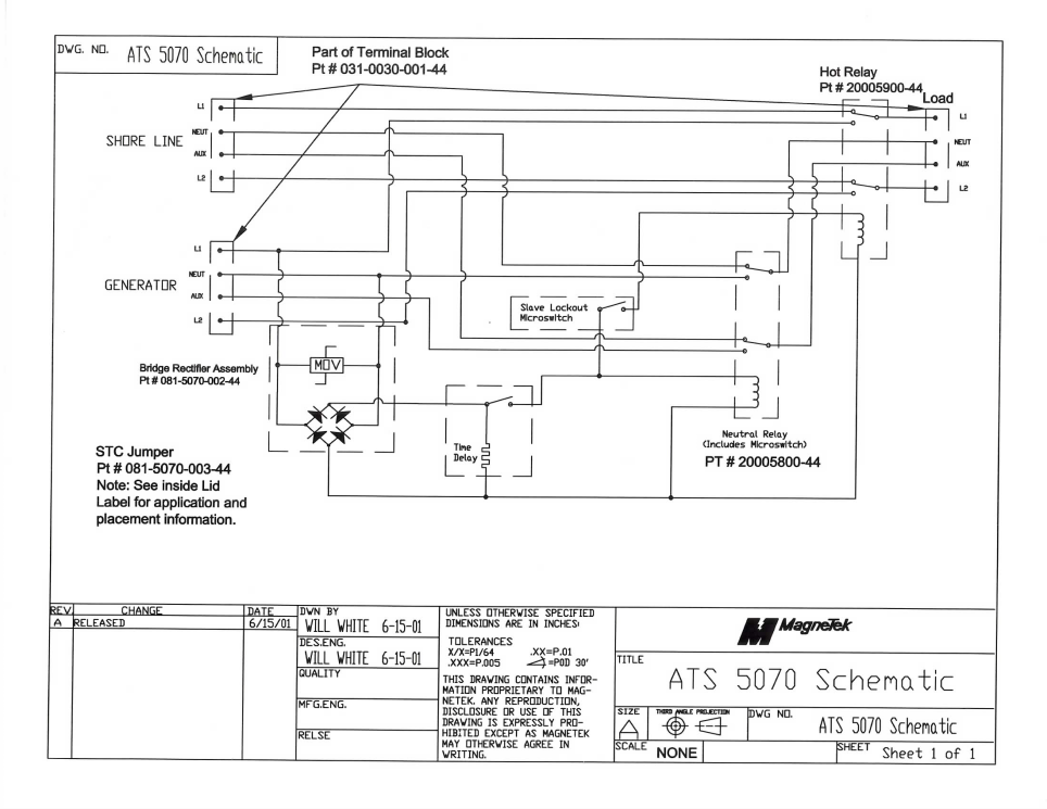
I was frustrated with not finding any useful circuit description on the Internet. I figured out the preceding information by observing my unit, tracing where the wires went, and observing printing on components like '+', '-', and 'AC' on the bridge Rectifier and 'NO' on the SPST switch. If I would have had the schematic diagram shown below, that would have made the diagnosis process much easier but at that time, I had not yet found that diagram. At this point, it confirms what I had determined. I provide it as a significant aid to other owners attempting to fix or maintain units that they own.
Be careful, observing appropriate safety precautions when working on electrical circuits and good luck.
Please send any corrections, comments or suggestions to: mike@mikebaker.com
I include the below ATS5070 Schematic Diagram because I was unable to relocate it after about 2 hours of Google searching. This is with the knowledge that it does exist out there somewhere! I think I originally found it off a link on some RV forum discussion page. Anyway, I was not able to refind it to included it as a link to that source.